 Sony FCB camera block

Overview
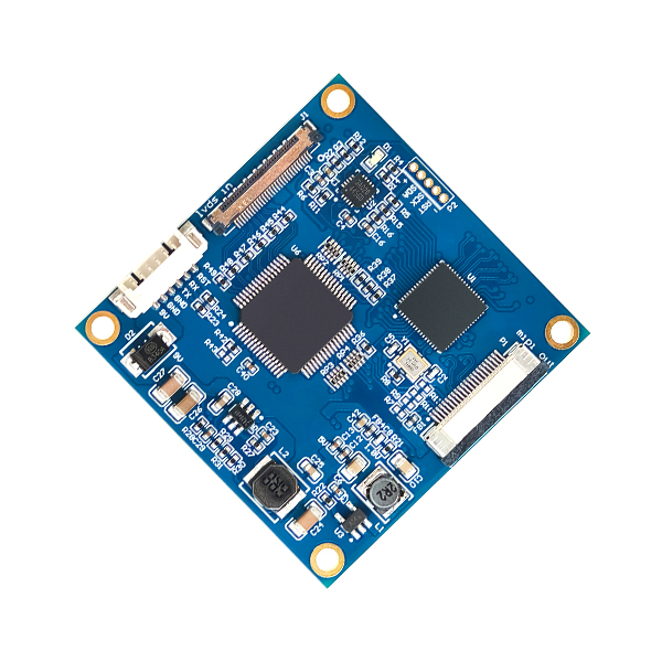
Custom-made for the entire series of Sony FCB high-definition block cameras. It connects the camera and the interface board via ultra-fine coaxial cables, accurately and efficiently converting the LVDS signals output by Sony FCB high-definition series cameras into MIPI signals, facilitating signal transmission and interaction between devices.
Features
- The MIPI signal format is CSI2, ensuring signal standardization.
- Accurately converts LVDS to MIPI signals to achieve efficient interface adaptation. With the above key features, the LVDS to MIPI interface board builds an efficient and stable bridge between the entire series of Sony FCB high-definition block cameras and devices supporting MIPI CSI2 interface. LVDS to MIPI Interface Board effectively solves the problem of signal format mismatch and meets the requirements for high-definition video image acquisition and transmission in different application scenarios.
- Hardware board only. No driver software included.
- Drivers available for separate purchase or self-development & optimization.
Supported Camera Modules And Video Formats
| Brand | Model | MIPI |
|
Sony |
FCB-EV9520L |
1080P60, 1080P50,1080P30,1080P25 720P60,720P50,720P30,720P25 |
| FCB-EV9500L | ||
| FCB-EV7520A | ||
| FCB-EV7520/CV7520 | ||
| FCB-EV7500/CV7500 | ||
|
Volers |
VRS-HD5101 | |
| VRS-HD5201 | ||
| VRS-HD5301 | ||
| VRS-HD5363 | ||
| VRS-HD5365 | ||
| Tamron | MP3010M-EV |
Note: This product works with Sony’s FCB HD cameras and other compatible camera blocks supporting Sony’s Visca-command.
Interface assignment
| Number | Pin Type | Pin definations |
| F1 | LVDS Socket | Camera LVDS interface connection |
| F2 | Molex Connector: Model 532610671, 6-pin socket with 1.25MM pitch | Interface definition see Table F2-1 |
| F3 | FPC Interface: 22-pin specification, 0.5MM pitch | Interface definition see Table F3-1 |
| Table: F2-1 | |||
| 1 | 9V-12V | 4 | TTL_TX |
| 2 | GND(9v-12v) | 5 | TTL_RX |
| 3 | GND | 6 | CAM_RST |
| Table: F3-1 | |||
| 1 | 3.3V | 12 | MIPI_TX2_N |
| 2 | I2C_SDA | 13 | GND |
| 3 | I2C_SCL | 14 | MIPI_CLK_P |
| 4 | GND | 15 | MIPI_CLK_N |
| 5 | NC | 16 | GND |
| 6 | NC | 17 | MIPI_TX1_P |
| 7 | GND | 18 | MIPI_TX1_N |
| 8 | MIPI_TX3_P | 19 | GND |
| 9 | MIPI_TX3_N | 20 | MIPI_TX0_P |
| 10 | GND | 21 | MIPI_TX0_N |
| 11 | MIPI_TX2_P | 22 | GND |
Front Side of the product
Procurement Model
| Model No. | Communication Method |
| PCB-HD305 | LVDS to MIPI conversion |
Product Accessories
 |
 |
 |
 |
| LVDS Coaxial Cable (80MM) Customizable Length
(Optional) |
6-Pin Terminal Wire (150MM)(Standard) | Screw/Copper pillar: M2*5 (Optional) | An iron plate (Size:50*50MM) (Optional) |
Interface Board on the Cameras

a. Interface board assembled with Sony Block camera FCB-EV9520L |

b. Interface board assembled with Sony Block camera FCB-EV9500L |

c. Interface board assembled with Sony Block camera FCB-EV7520 |
Note: The product supports individual purchase or “block camera+interface board” package purchase. The whole set comes without pre-installation by default. Specify installation needs when ordering.
Installation steps
Preparation
|
|
|
|
|
| Exemplified by FCB-EV9520L | 30Pin LVDS Coaxial Cable | 6pin terminal wire | Screw/Copper pillars | Iron Plate |
Connection Steps
Physical Assembly Steps Only (No Electrical Work)
Notes: The steps demonstrate physical connection only-electrical connection is excluded. No image output at this stage. For electrical connection assistance, contact technical support.
 |
 |
 |
 |
| StepⅠ:
1. Install four copper pillars onto the iron plate (as shown in Figure ① above). 2. Install the iron plate onto the rear of the camera and tighten the screws (as shown in Figure ② above). |
StepⅡ: Connect one terminal of the 30-pin micro coaxial cable to the HD block camera (as shown in Figure ③ above).4. Connect the other terminal of the 30-pin micro coaxial cable to the interface board (as shown in Figure ④ above).Caution: Plug in the micro coaxial cable with gold-plated pins on camera facing up. Reverse insertion is strictly prohibited. |
Step Ⅲ: 5. Install the interface board at the rear of the block camera and tighten the screws.(as shown in Figure ⑤ above). |
Step Ⅳ: 6. Physically connect the LVDS to MIPI interface board with the 6-pin terminal wire (as shown in Figure ⑥ above). |
Thank you very much for purchasing our company’s products. If you have any questions, please feel free to contact us.
The photos and actual objects depicted in this Manual are provided solely for reference and guidance to users.
We do not guarantee that they are completely identical to the actual products. Please refer to the actual products.
Design, features and specifications are subject to change without notice.